Mycelium v2: building the edge-peripheral device
Building a efficient ESP32 edge device for Mycelium v2
What is a peripheral?
In the Mycelium v2 ecosystem, edge devices are the sensory and controlling printed circuit boards. These peripherals are battery-powered ESP32 modules that live alongside your plants, constantly monitoring their environment. But here’s the challenge: these devices need to run for months on two AA batteries charge while maintaining reliable communication, watering and accurate sensing.
Architecture pivot from v1
To accomplish this, we moved away from an architecture where the hardware peripheral connects via WiFi directly the cloud backend. Instead we use Bluetooth Low Energy (BLE) to send the data to another device which is always on, called edge-central.
To connect and authenticate with WiFi can be resource intensive and the connection to any HTTP + TLS service as well (as you need encryption). Other companies like Philips Hue and Tado are also using with a hub (central) architecture which is more power efficient.

INFO
The communication to the cloud is pushed to the edge-central, which is single board computer (SBC) which is more powerful and is always on and connected to a power supply. The central initially needs to be onboarded, as it doesn’t have WiFi or Auth0 setup. So if the central doesn’t have any state regarding WiFi or Auth0 it will also be BLE peripheral where your phone or desktop tries to connect to via BLE. More about the edge-central in the next blog post.
Bluetooth central vs Bluetooth peripheral
In the following picture you’ll see a central communicating with a peripheral.
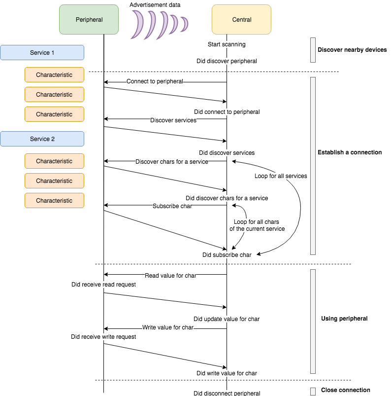
A BLE central is a device that initiates and manages connections with BLE peripherals (like our ESP32 sensors). It scans for nearby devices, establishes connections, and can read/write data from multiple peripherals simultaneously. In our case, the central acts as a bridge—collecting sensor data from all the ESP32 edge devices and forwarding it to the cloud backend, while also distributing commands or configuration updates back to the peripherals.
A BLE peripheral, on the other hand, is a device that advertises its presence and waits for connections from centrals. Peripherals expose their functionality through services and characteristics that centrals can discover and interact with. Our ESP32 edge devices act as peripherals—they broadcast their availability, accept connections from the central, and provide sensor data when requested. Peripherals are typically simpler devices focused on specific tasks, making them ideal for our battery-powered sensors. But in our case central also is a peripheral while onboarding.
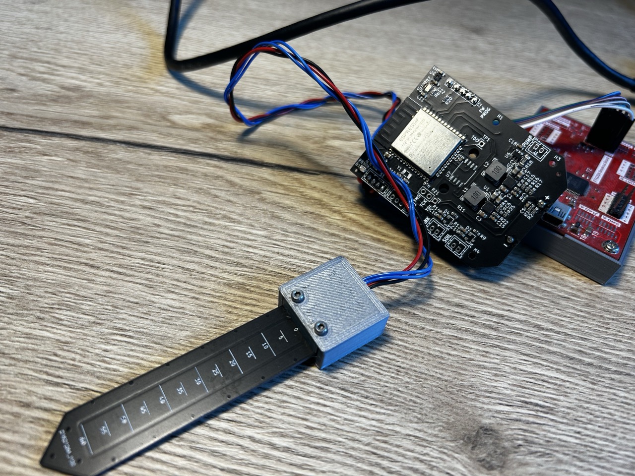
What did we install on our printed circuit board (PCB) ?
Like I’ve mentioned in the start of the series, my brother Hans de Jong did the design of the PCB. We’ve used the following components which are all connected to the microcontroller ESP32. There are different protocols you can use in embedded systems, but we only need to use I2C.
- ESP32-WROOM - This is the brain of the PCB, which will run the firmware program and reads the sensors and does stuff accordingly with it.
- BH1730FVC - For measuring lux
- SHTC3X - For humidity and temperature
- Custom soil moisture sensor, which has it’s own microcontroller. This also exchanges information through i2c
INFO
How do we plan to achieve power efficiency?
- We will use ESP32 deep sleep. Deep sleep is a power-saving mode where the microcontroller shuts down almost all of its components—the CPU stops executing code, RAM is powered down, and most peripherals are disabled. Only a small portion of the system remains active to wake the device up at predetermined intervals or when specific events occur (like a timer or external interrupt). During deep sleep, the ESP32 consumes only microamps of current instead of the normal 80-240mA, extending battery life from days to months. We plan to sample measurements every 10 minutes
- Additionally, using BLE instead of WiFi provides significant power savings according to this sheet. While WiFi requires the ESP32 to maintain a constant connection and perform regular keep-alive transmissions, BLE is designed for devices to quickly connect, exchange data, and disconnect—all while consuming much less power. WiFi operations can draw 240mA during transmission with an ESP32 according to the specification, whereas BLE typically uses only 95-100mA, making it ideal for our battery-powered edge devices.
- We implement a custom deviation-based time series compression library directly in the firmware, closely resembling the Swinging Door Compression algorithm. This compression system maintains a compressed array of sensor readings in the ESP32’s RTC (Real-Time Clock) memory, which remains powered even during deep sleep cycles. By only storing data points that deviate significantly from the predicted trend line, we can dramatically reduce the amount of data that needs to be transmitted over BLE while preserving the essential patterns in our sensor measurements. This approach allows us to buffer multiple readings between wake cycles and transmit only the most meaningful data points to the central device.
Here’s how the cycle works:
- Wake up every 10 minutes from deep sleep
- Read sensors via I2C (light, temperature, humidity, soil moisture)
- Compress and buffer the data using our deviation-based algorithm in RTC memory
- Check buffer capacity - if we have 6 entries, proceed to transmission
- Advertise via BLE - broadcast our presence so the central can discover us
- Transmit buffered data when the central connects and requests it
- Clear buffer after successful transmission
- Return to deep sleep for another 10-minute cycle
Next steps
Now that we have our PCB assembled with all the necessary components, the next step is programming the firmware onto the ESP32 microcontroller. This involves using a programmer to flash our custom code that will handle sensor readings, BLE communication, and power management. The firmware will orchestrate everything we’ve discussed—from deep sleep cycles to I2C sensor communication and BLE data transmission to the central device. In the next blog post, we’ll dive into the firmware development process, exploring how we implement the power-efficient sensor monitoring loop and establish reliable BLE communication protocols.
📚 Posts in this series: Mycelium v2
- 1 Introducing Mycelium v2: A smarter way to water and monitor plants
- 2 CI/CD Pipelines: Choosing the Right Tool
- 3 Mycelium v2: building the edge-peripheral device (current)
- 4 Mycelium v2: firmware for the edge-peripheral device
- 5 Mycelium v2: measuring efficiency of edge-peripheral